Your technical, product, or application questions answered in one business day* by our team of experts.
! Please fill in all fields before submitting your question. Pepperl+Fuchs values your privacy. Please read our privacy policy.
* Pepperl+Fuchs makes every effort to provide an answer that is helpful and relevant to you. Your question is typically answered in one business day. Occasionally, an answer is delayed. In these cases, we are often researching your question, conferring with colleagues, or may route your question to another Pepperl+Fuchs location. You will be notified via e-mail regarding the status of your question.
Please note: All product-related documents, such as certificates, declarations of conformity, etc., which were issued prior to the conversion under the name Pepperl+Fuchs GmbH or Pepperl+Fuchs AG, also apply to Pepperl+Fuchs SE.
Download the complete datasheet as a PDF:
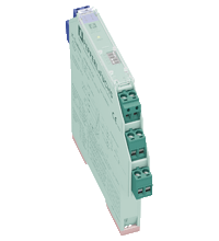
Datasheet excerpt: Technical data of
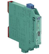
KCD2-SR-Ex1.LB
253 V AC/2 A/cos φ > 0.7; 126.5 V AC/4 A/cos φ > 0.7; 30 V DC/2 A resistive load
Minimum switch current
2 mA / 24 V DC
Energized/De-energized delay
≤ 20 ms / ≤ 20 ms
Mechanical life
107 switching cycles
Transfer characteristics
Switching frequency
≤ 10 Hz
Galvanic isolation
Input/Output
reinforced insulation acc. to EN 50178, rated insulation voltage 300 Veff
Input/power supply
reinforced insulation acc. to EN 50178, rated insulation voltage 300 Veff
Output/power supply
reinforced insulation acc. to EN 50178, rated insulation voltage 300 Veff
Output/Output
reinforced insulation acc. to EN 50178, rated insulation voltage 300 Veff
Indicators/settings
Display elements
LEDs
Control elements
DIP switch
Configuration
via DIP switches
Labeling
space for labeling at the front
Directive conformity
Electromagnetic compatibility
Directive 2014/30/EU
EN 61326-1:2013 (industrial locations)
Low voltage
Directive 2014/35/EU
EN 61010-1:2010
Conformity
Electromagnetic compatibility
NE 21
Degree of protection
IEC 60529:2001
Ambient conditions
Ambient temperature
-20 ... 60 °C (-4 ... 140 °F)
Mechanical specifications
Degree of protection
IP20
Connection
screw terminals
Mass
approx. 100 g
Dimensions
12.5 x 119 x 114 mm (0.5 x 4.7 x 4.5 inch) (W x H x D) , housing type A2
Height
119 mm
Width
12.5 mm
Depth
114 mm
Mounting
on 35 mm DIN mounting rail acc. to EN 60715:2001
Data for application in connection with hazardous areas
EU-type examination certificate
BASEEFA 06 ATEX 0092
Marking
II (1)G [Ex ia Ga] IIC , II (1)D [Ex ia Da] IIIC , I (M1) [Ex ia Ma] I
Input
[Ex ia Ga] IIC, [Ex ia Da] IIIC, [Ex ia Ma] I
Voltage
10.5 V
Current
17.1 mA
Power
45 mW (linear characteristic)
Supply
Maximum safe voltage
253 V AC (Attention! Um is no rated voltage.)
Output I, II
Maximum safe voltage
253 V AC (Attention! Um is no rated voltage.)
Contact loading
253 V AC/2 A/cos φ > 0.7; 126.5 V AC/4 A/cos φ > 0.7; 30 V DC/2 A resistive load
Certificate
PF 06 CERT 0972 X
Marking
II 3G Ex nA nC IIC T4 Gc
Output I, II
Contact loading
50 V AC/2 A/cos φ > 0.7; 30 V DC/2 A resistive load
Galvanic isolation
Input/Output
safe electrical isolation acc. to IEC/EN 60079-11, voltage peak value 375 V
Input/power supply
safe electrical isolation acc. to IEC/EN 60079-11, voltage peak value 375 V
Directive conformity
Directive 2014/34/EU
EN 60079-0:2012+A11:2013 , EN 60079-11:2012 , EN 60079-15:2010
International approvals
FM approval
Control drawing
116-0419 (cFMus)
UL approval
Control drawing
116-0420 (cULus)
IECEx approval
IECEx certificate
IECEx BAS 06.0025
IECEx marking
[Ex ia Ga] IIC [Ex ia Da] IIIC [Ex ia Ma] I
General information
Supplementary information
Observe the certificates, declarations of conformity, instruction manuals, and manuals where applicable. For information see www.pepperl-fuchs.com.
Classifications
System
Classcode
ECLASS 13.0
27210121
ECLASS 12.0
27210121
ECLASS 11.0
27210121
ECLASS 10.0.1
27210121
ECLASS 9.0
27210121
ECLASS 8.0
27210121
ECLASS 5.1
27210121
ETIM 9.0
EC001485
ETIM 8.0
EC001485
ETIM 7.0
EC001485
ETIM 6.0
EC001485
ETIM 5.0
EC001485
UNSPSC 12.1
32101514
Details:
KCD2-SR-Ex1.LB
Function
This isolated barrier is used for intrinsic safety applications.
The device transfers digital signals from NAMUR sensors or dry contacts from the hazardous area to the non-hazardous area.
The proximity sensor or the mechanical contact controls the control side load for a relay contact output. The device output changes the state when the input signal changes the state.
Via switches the mode of operation can be reversed and the line fault detection can be switched off.
During a fault condition, the relay reverts to its de-energized state and the LEDs indicate the fault according to NAMUR NE 44.
If the device is operated via Power Rail, additionally a collective error message is available.
Due to its compact housing design and low heat dissipation, this device is useful for detecting positions, end stops, and switching states in space-critical applications.
Netlist price. Your individual price will be calculated during checkout.
In stock
Item 'UPR-03' added to cart!
35 mm DIN mounting rail with 3-conductor insert, Provides DC supply voltage to all equipped K-System modules, Standard length 2 m (6 foot), simple to customize to application space, Eliminates daisy-chainspa
35 mm DIN mounting rail with 3-conductor insert, Provides DC supply voltage to all equipped K-System modules, Standard length 1.6 m (5 foot), simple to customize to application space, Eliminates daisy-chainspa
Netlist price. Your individual price will be calculated during checkout.
In stock
Item 'UPR-03-S' added to cart!
35 mm DIN mounting rail with 3-conductor insert, Provides DC supply voltage to all equipped K-System modules, Standard length 0.8 m (2.6 ft), simple to customize to application space, Eliminates daisy-chainspa
Cable trunking is integrated in the mounting profile, Safe spacious separation of safe and hazardous signals, No additional cable guides necessary, Standard length 1.8 m (5.8 ft), simple to customize to application space, With mounting aidspa
Cable trunking with integrated Power Rail UPR-03, Safe spacious separation of safe and hazardous signals, No additional cable guides necessary, Provides DC supply voltage to all equipped K-System modules, Standard length 1.8 m (5.8 ft), simple to customize to application space, With end caps UPR-E, cover and mounting aidspa
Choose from various selection criteria like safety integrity level, performance level, device function, and signal type and find the SIL/PL assessed device that you are looking for.


 Contact Us
 II (1)G [Ex ia Ga] IIC ,


 +1 330 425-3555