

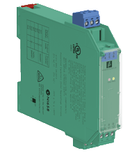
SMART Current Driver KFD2-SCD-Ex1.LK
- 1-channel isolated barrier
- 24 V DC supply (Power Rail)
- Current output up to 700 Ω load
- HART I/P and valve positioner
- Line fault detection (LFD)
- Accuracy 0.1 %
- Terminal blocks with test sockets
- Up to SIL 2 acc. to IEC 61508


 Contact Us
Please note: All product-related documents, such as certificates, declarations of conformity, etc., which were issued prior to the conversion under the name Pepperl+Fuchs GmbH or Pepperl+Fuchs AG, also apply to Pepperl+Fuchs SE.
Download the complete datasheet as a PDF:
Datasheet excerpt: Technical data of KFD2-SCD-Ex1.LK
| General specifications | ||
|---|---|---|
| Signal type | Analog output | |
| Functional safety related parameters | ||
| Safety Integrity Level (SIL) | SIL 2 | |
| Supply | ||
| Connection | Power Rail or terminals 11+, 12- | |
| Rated voltage | 20 ... 35 V DC | |
| Ripple | within the supply tolerance | |
| Power dissipation | 1.1 W at 20 mA into 10 V (equivalent to 500 Ω) load | |
| Power consumption | 1.3 W | |
| Input | ||
| Connection side | control side | |
| Connection | terminals 7-, 8+ | |
| Voltage drop | approx. 4 V or internal resistance 200 Ω at 20 mA | |
| Input resistance | > 100 kΩ, when wiring resistance in the field < 50 Ω or > 800 Ω at 20 mA | |
| Current | 4 ... 20 mA limited to approx. 25 mA | |
| Output | ||
| Connection side | field side | |
| Connection | terminals 1+, 2- | |
| Voltage | ≥ 14 V at 20 mA | |
| Current | 4 ... 20 mA | |
| Load | 100 ... 700 Ω | |
| Transfer characteristics | ||
| Accuracy | 0.1 % | |
| Deviation | ||
| After calibration | at 20 °C (68 °F): ≤ ± 0.1 % incl. non-linearity and hysteresis | |
| Influence of ambient temperature | ≤ ± 20 ppm/K | |
| Rise time | < 100 µs at bounce from 10 ... 90 % | |
| Galvanic isolation | ||
| Input/power supply | basic insulation acc. to EN 50178, rated insulation voltage of 50 V AC | |
| Indicators/settings | ||
| Display elements | LEDs | |
| Labeling | space for labeling at the front | |
| Directive conformity | ||
| Electromagnetic compatibility | ||
| Directive 2014/30/EU | EN 61326-1:2013 (industrial locations) | |
| Conformity | ||
| Insulation coordination | EN 50178:1997 | |
| Galvanic isolation | EN 50178:1997 | |
| Electromagnetic compatibility | NE 21:2006 | |
| Degree of protection | IEC 60529:2001 | |
| Ambient conditions | ||
| Ambient temperature | -20 ... 60 °C (-4 ... 140 °F) | |
| Mechanical specifications | ||
| Degree of protection | IP20 | |
| Connection | screw terminals | |
| Mass | approx. 100 g | |
| Dimensions | 20 x 115 x 115 mm (0.8 x 4.5 x 4.5 inch) , housing type B1 | |
| Height | 115 mm | |
| Width | 20 mm | |
| Length | 115 mm | |
| Mounting | on 35 mm DIN mounting rail acc. to EN 60715:2001 | |
| Data for application in connection with hazardous areas | ||
| EU-type examination certificate | BAS 00 ATEX 7215 | |
| Marking |  II (1)G [Ex ia Ga] IIC , II (1)D [Ex ia Da] IIIC , I (M1) [Ex ia Ma] I II (1)G [Ex ia Ga] IIC , II (1)D [Ex ia Da] IIIC , I (M1) [Ex ia Ma] I |
|
| Output | Ex ia IIC, Ex iaD | |
| Voltage | 25.2 V | |
| Current | 93 mA | |
| Power | 0.58 W | |
| Supply | ||
| Maximum safe voltage | 250 V rms (Attention! The rated voltage can be lower.) | |
| Certificate | TÜV 99 ATEX 1499 X | |
| Marking | II 3G Ex nA II T4 [device in zone 2] |
|
| Galvanic isolation | ||
| Input/Output | safe electrical isolation acc. to EN 60079-11, voltage peak value 375 V | |
| Output/power supply | safe electrical isolation acc. to EN 60079-11, voltage peak value 375 V | |
| Directive conformity | ||
| Directive 2014/34/EU | EN 60079-0:2012+A11:2013 , EN 60079-11:2012 , EN 60079-15:2010 | |
| International approvals | ||
| FM approval | ||
| Control drawing | 116-0129 | |
| UL approval | ||
| Control drawing | 116-0173 (cULus) | |
| IECEx approval | IECEx BAS 16.0045 | |
| Approved for | [Ex ia Ga] IIC, [Ex ia Da] IIIC, [Ex ia Ma] I | |
| General information | ||
| Supplementary information | Observe the certificates, declarations of conformity, instruction manuals, and manuals where applicable. For information see www.pepperl-fuchs.com. | |
| Accessories | ||
| Optional accessories | - power feed module KFD2-EB2(.R4A.B)(.SP) - universal power rail UPR-03(-M)(-S) - profile rail K-DUCT-BU(-UPR-03) |
|
Classifications
| System | Classcode |
|---|---|
| ECLASS 13.0 | 27210120 |
| ECLASS 12.0 | 27210120 |
| ECLASS 11.0 | 27210120 |
| ECLASS 10.0.1 | 27210120 |
| ECLASS 9.0 | 27210120 |
| ECLASS 8.0 | 27210120 |
| ECLASS 5.1 | 27210120 |
| ETIM 9.0 | EC002653 |
| ETIM 8.0 | EC002653 |
| ETIM 7.0 | EC002653 |
| ETIM 6.0 | EC002653 |
| ETIM 5.0 | EC001485 |
| UNSPSC 12.1 | 32101514 |
Details: KFD2-SCD-Ex1.LK
Function
This isolated barrier is used for intrinsic safety applications. It drives SMART I/P converters, electrical valves, and positioners in hazardous areas.
Digital signals are superimposed on the analog values at the field or control side and are transferred bi-directionally.
Current transferred across the DC/DC converter is repeated at terminals 1 and 2.
An open field circuit presents a high input impedance to the control side to allow lead breakage monitoring by control system.
If the loop resistance for the digital communication is too low, an internal resistor of 250 Ω between terminals 8 and 9 is available, which may be used as the HART communication resistor.
Sockets for the connection of a HART communicator are integrated into the terminals of the device.
Product Documentation: KFD2-SCD-Ex1.LK
| Safety and Security Documentation | Language | File Type | File Size |
|---|---|---|---|
| Instruction manual | ENG | 50 KB | |
| Manuals | |||
| Manual | ENG | 3685 KB | |
Design / Simulation: KFD2-SCD-Ex1.LK
| CAD | Language | File Type | File Size |
|---|---|---|---|
| CAD 2-D / CAD 2-D | ALL | ZIP | 450 KB |
| CAD 3-D / CAD 3-D | ALL | STP | 105 KB |
| CAE | |||
| CAE EPLAN Data Portal / CAE EPLAN Data Portal | ALL | LINK | --- |
| EPLAN macro EDZ / EPLAN Makro EDZ | ALL | EDZ | 55 KB |
Approvals: KFD2-SCD-Ex1.LK
| Certificates | Certificate No. | Language | File Type | File Size |
|---|---|---|---|---|
| Baseefa IECEx Certificate of Conformity | IECEx BAS 16.0045 | ALL | LINK | --- |
| Canada UL cUL | E106378 cUL (QUZW7) | ALL | LINK | --- |
| Europe Baseefa II (1) D I (M1) II (1) G | BAS 00 ATEX 7215 | ALL | 2524 KB | |
| Europe TUV Nord ATEX Category 3 G | TÜV 99 ATEX 1499X | ALL | 1999 KB | |
| Korea KOSHA | 19-AV4BO-0026 | ALL | 100 KB | |
| USA Canada UL Hazardous Location Certificate of Compliance cULus UL E106378 | CoC 20140902 - E106378 RepRef 20011030 | ALL | 429 KB | |
| USA FM | CoC 1Z2A1.AX | ALL | 78 KB | |
| USA UL | E106378 UL (QUZW) | ALL | LINK | --- |
| exida Functional Safety Assessment | P+F 03/10-12 R014 | ALL | 302 KB | |
| Control Drawings | ||||
| Control drawing UL / Control drawing UL | ALL | 1092 KB | ||
| Control drawing FM / Control drawing FM | ALL | 58 KB | ||
| Declaration of Conformity | ||||
| EU Declaration of Conformity (P+F) / EU-Konformitäterklärung (P+F) | DOC-0782B | ALL | 55 KB | |
Associated Products: KFD2-SCD-Ex1.LK
| Accessories | ||||||
|---|---|---|---|---|---|---|
|
||||||
|
||||||
|
||||||
|
||||||
|
||||||
|
||||||
|
||||||
|
||||||
|
||||||


- Ask an Expert
- Cross Reference Request
- Check order status
- News
- Subscribe to Gate-Way, our Process Automation Division e-newsletter
- Service Level Agreements for ecom instruments
- Where to Buy our Products
- Browse Literature
- Technologies
- Control System Solutions
- Download Technical Documents
- Press Releases
- International Trade Shows

Choose from various selection criteria like safety integrity level, performance level, device function, and signal type and find the SIL/PL assessed device that you are looking for.


Pepperl+Fuchs Inc.
1600 Enterprise Parkway
Twinsburg, OH 44087
USA
- responsible for Canada -
sales@us.pepperl-fuchs.com
 +1 330 425-3555
Pepperl+Fuchs is a leading developer and manufacturer of electronic sensors and components for the global automation market. Continuous innovation, enduring quality, and steady growth have been the foundation of our success for more than 70 years. Pepperl+Fuchs employs 6,300 people worldwide and has manufacturing facilities in Germany, USA, Singapore, Hungary, Indonesia and Vietnam, most of them ISO 9001 certified.