

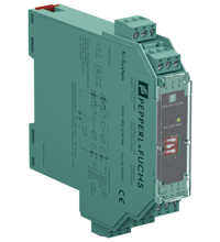
Standstill and Rotational Direction Monitor KFD2-SR2-2.W.SM
- 2-channel signal conditioner
- 24 V DC supply
- PNP/push-pull, dry contacts or NAMUR inputs
- Selectable frequency trip values
- 2 relay contact outputs
- Start-up override
- Selectable mode of operation
- Without line fault detection
- Up to SIL 2 acc. to IEC/EN 61508


Please note: All product-related documents, such as certificates, declarations of conformity, etc., which were issued prior to the conversion under the name Pepperl+Fuchs GmbH or Pepperl+Fuchs AG, also apply to Pepperl+Fuchs SE.
Datasheet excerpt: Technical data of KFD2-SR2-2.W.SM
| General specifications | ||
|---|---|---|
| Signal type | Digital Input | |
| Programming | via DIP switch and programmable | |
| Functional safety related parameters | ||
| Safety Integrity Level (SIL) | SIL 2 | |
| Supply | ||
| Connection | terminals 14+, 15- | |
| Rated voltage | 20 ... 30 V DC | |
| Power consumption | max. 1.5 W | |
| Input | ||
| Connection side | field side | |
| Connection | Input I: terminals 1+, 2+, 3- ; Input II: terminals 4+, 5+, 6- |
|
| Rated values | acc. to EN 60947-5-6 (NAMUR) | |
| Open circuit voltage/short-circuit current | approx. 8 V DC / approx. 8 mA | |
| Switching point/switching hysteresis | 1.2 ... 2.1 mA / approx. 0.2 mA | |
| Line fault detection | not available | |
| Control input | sensor power supply approx. 8.2 V, impedance 1.2 kΩ | |
| Pulse duration | > 200 µs for standstill monitoring, > 250 µs for rotation direction detecion |
|
| Output | ||
| Connection side | control side | |
| Connection | output I: terminals 7, 8, 9 ; output II: terminals 10, 11, 12 |
|
| Contact loading | 253 V AC/2 A/cos φ > 0.7; 126.5 V AC/4 A/cos φ > 0.7; 40 V DC/2 A resistive load | |
| Minimum switch current | 2 mA / 24 V DC | |
| Energized/De-energized delay | approx. 20 ms / approx. 20 ms | |
| Mechanical life | 107 switching cycles | |
| Trip value | for standstill monitoring: 0.1 Hz; 0.5 Hz; 2 Hz; 10 Hz adjustable via DIP switch (S1 and S2) |
|
| Transfer characteristics | ||
| Accuracy | 5 % (S3 = I), 30 % (S3 = II) | |
| Start-up override | 5 seconds or 20 seconds, programmable | |
| Frequency range | ≤ 2 kHz | |
| Rotation direction detection | 90° phase difference between pulse input signal 1 and 2, overlapping ≥ 125 µs | |
| Galvanic isolation | ||
| Input/Output | reinforced insulation according to IEC/EN 61010-1, rated insulation voltage 300 Veff | |
| Input/power supply | reinforced insulation according to IEC/EN 61010-1, rated insulation voltage 300 Veff | |
| Output/power supply | reinforced insulation according to IEC/EN 61010-1, rated insulation voltage 300 Veff | |
| Output/Output | reinforced insulation according to IEC/EN 61010-1, rated insulation voltage 300 Veff | |
| Indicators/settings | ||
| Display elements | LEDs | |
| Control elements | DIP switch | |
| Configuration | via DIP switches | |
| Labeling | space for labeling at the front | |
| Directive conformity | ||
| Electromagnetic compatibility | ||
| Directive 2014/30/EU | EN 61326-1:2013 (industrial locations) | |
| Low voltage | ||
| Directive 2014/35/EU | EN 61010-1:2010 | |
| Conformity | ||
| Electromagnetic compatibility | NE 21:2006 | |
| Degree of protection | IEC 60529:2001 | |
| Input | EN 60947-5-6:2000 | |
| Ambient conditions | ||
| Ambient temperature | -20 ... 60 °C (-4 ... 140 °F) | |
| Mechanical specifications | ||
| Degree of protection | IP20 | |
| Connection | screw terminals | |
| Mass | approx. 150 g | |
| Dimensions | 20 x 119 x 115 mm (0.8 x 4.7 x 4.5 inch) (W x H x D) , housing type B2 | |
| Height | 119 mm | |
| Width | 20 mm | |
| Depth | 115 mm | |
| Mounting | on 35 mm DIN mounting rail acc. to EN 60715:2001 | |
| General information | ||
| Supplementary information | Observe the certificates, declarations of conformity, instruction manuals, and manuals where applicable. For information see www.pepperl-fuchs.com. | |
Classifications
| System | Classcode |
|---|---|
| ECLASS 13.0 | 27210128 |
| ECLASS 12.0 | 27210128 |
| ECLASS 11.0 | 27210128 |
| ECLASS 10.0.1 | 27210128 |
| ECLASS 9.0 | 27210128 |
| ECLASS 8.0 | 27210190 |
| ECLASS 5.1 | 27210121 |
| ETIM 9.0 | EC002918 |
| ETIM 8.0 | EC002918 |
| ETIM 7.0 | EC002918 |
| ETIM 6.0 | EC002918 |
| ETIM 5.0 | EC002475 |
| UNSPSC 12.1 | 39121007 |
Details: KFD2-SR2-2.W.SM
This signal conditioner provides the galvanic isolation between field circuits and control circuits.
This device is a standstill monitor that accepts input frequency pulses and triggers an output when the frequency drops below a preselected limit value.
Two start-up override values are available. This unit can also be used to determine rotation direction.
During an error condition or a power loss, the relay reverts to its de-energized state and the LEDs indicate the fault according to NAMUR NE 44. A line fault is not indicated.
The device has LED status indicators for direction of rotation detection, limit detection, supply, and hardware faults.
The device is easily configured by the use of DIP switches.
For additional information, refer to www.pepperl-fuchs.com.
Datasheet: KFD2-SR2-2.W.SM
| Datasheet | File Type | File Size |
|---|---|---|
| Datasheet KFD2-SR2-2.W.SM | 1273 KB | |
| Fiche de données KFD2-SR2-2.W.SM | 1188 KB | |
| Datenblatt KFD2-SR2-2.W.SM | 1181 KB | |
| Datasheet KFD2-SR2-2.W.SM | 1394 KB | |
| Hoja de datos KFD2-SR2-2.W.SM | 1195 KB |
Documents: KFD2-SR2-2.W.SM
CAD+CAE: KFD2-SR2-2.W.SM
| CAD | File Type | File Size |
|---|---|---|
| CAD 3-D / CAD 3-D | STP | 2510 KB |
| CAD Portal / CAD Portal | LINK | --- |
| EPLAN | ||
| EPLAN macro EDZ / EPLAN Makro EDZ | EDZ | 64 KB |
Approvals+Certificates: KFD2-SR2-2.W.SM
| Certificates | File Type | File Size |
|---|---|---|
| exida Functional Safety Assessment | 148 KB | |
| Declaration of Conformity | ||
| EU Declaration of Conformity (P+F) / EU-Konformitäterklärung (P+F) | 115 KB |
Associated Products: KFD2-SR2-2.W.SM
| Matching System Components | ||||||
|---|---|---|---|---|---|---|
|
||||||
|
||||||
|
||||||
|
||||||
|
||||||
|
||||||
| Accessories | ||||||
|
||||||
|
||||||
|
||||||


Pepperl+Fuchs SE
Lilienthalstraße 200
68307 Mannheim
Germany
info@de.pepperl-fuchs.com
 +49 621 776-0
Pepperl+Fuchs is a leading developer and manufacturer of electronic sensors and components for the global automation market. Continuous innovation, enduring quality, and steady growth have been the foundation of our success for more than 70 years. Pepperl+Fuchs employs 6,300 people worldwide and has manufacturing facilities in Germany, USA, Singapore, Hungary, Indonesia and Vietnam, most of them ISO 9001 certified.