

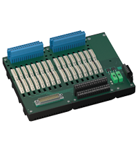
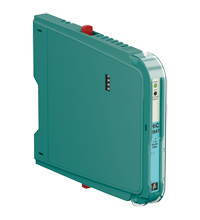
Termination Board HiCTB16-TRX-RAS-PL-IO16
- System board for Schneider Electric, Tricon CX series by Triconex
- For 16-channel universal I/O card 3902(A)X
- For 16 modules
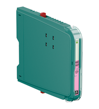
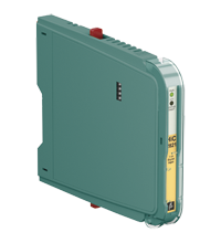
- Recommended modules: HiC2027 (AI), HiC2027ES (AI), HiC2821 (DI), HiC2831R4 (DI), HiC2841 (DI), HiC2853R4 (DI)
- 24 V DC supply
- Hazardous area: pluggable screw terminals, blue
- Non-hazardous area: screw terminals, black
- Non-hazardous area: Sub-D connector (male), 50-pin
- Up to SIL 3 acc. to IEC/EN 61508


 Contact Us
Please note: All product-related documents, such as certificates, declarations of conformity, etc., which were issued prior to the conversion under the name Pepperl+Fuchs GmbH or Pepperl+Fuchs AG, also apply to Pepperl+Fuchs SE.
Datasheet excerpt: Technical data of HiCTB16-TRX-RAS-PL-IO16
| Functional safety related parameters | ||
|---|---|---|
| Safety Integrity Level (SIL) | SIL 3 | |
| Systematic capability (SC) | SC 3 | |
| Supply | ||
| Connection | X20: terminals 3, 5(+); 4, 6(-) | |
| Nominal voltage | 24 V DC , in consideration of rated voltage of used isolators | |
| Voltage drop | 0.9 V , voltage drop across the series diode on the termination board must be considered | |
| Ripple | ≤ 10 % | |
| Fusing | 4 A , in each case for 16 modules | |
| Power dissipation | ≤ 500 mW , without modules | |
| Reverse polarity protection | yes | |
| Redundancy | ||
| Supply | Redundancy available. The supply for the isolators is decoupled, monitored and fused. | |
| Fault indication output | ||
| Connection | X20: terminals 1(+), 2(-) | |
| Output type | volt-free transistor output , not short-circuit protected , not overload protected | |
| Rated voltage | 30 V DC | |
| Rated current | 100 mA | |
| Signal level | no fault: (external voltage) - 1 V max. for 100 mA (Tamb = 25 °C (77 °F)) power supply fault/module fault: blocked output (off-state current ≤ 10 µA) |
|
| Indicators/settings | ||
| Display elements | LED PWR1 (termination board power supply), green LED LED PWR2 (termination board power supply), green LED |
|
| Directive conformity | ||
| Electromagnetic compatibility | ||
| Directive 2014/30/EU | EN 61326-1:2013 (industrial locations) | |
| Conformity | ||
| Electromagnetic compatibility | EN IEC 61326-3-2:2018 , NE 21:2017 For further information see system description. |
|
| Degree of protection | IEC 60529:2001 | |
| Ambient conditions | ||
| Ambient temperature | -20 ... 60 °C (-4 ... 140 °F) | |
| Storage temperature | -40 ... 85 °C (-40 ... 185 °F) | |
| Mechanical specifications | ||
| Degree of protection | IP20 | |
| Connection | ||
| Field side | explosion hazardous area: pluggable screw terminals , blue | |
| Control side | non-explosion hazardous area: output I: 50-pin Sub-D connector output II: screw terminals , black |
|
| Supply | pluggable screw terminals , black | |
| Fault output | pluggable screw terminals , black | |
| Core cross section | screw terminals 0.25 ... 2.5 mm2 (24 ... 12 AWG) | |
| Material | housing: polycarbonate, 10 % glass fiber reinforced | |
| Mass | approx. 935 g | |
| Dimensions | 266 x 200 x 163 mm (10.5 x 7.9 x 6.42 inch) (W x H x D) , depth including module assembly | |
| Height | 200 mm | |
| Width | 266 mm | |
| Depth | 163 mm | |
| Mounting | on 35 mm DIN mounting rail acc. to EN 60715:2001 | |
| Data for application in connection with hazardous areas | ||
| EU-type examination certificate | CESI 06 ATEX 022 | |
| Marking |  II (1)G [Ex ia Ga] IIC II (1)D [Ex ia Da] IIIC I (M1) [Ex ia Ma] I II (1)G [Ex ia Ga] IIC II (1)D [Ex ia Da] IIIC I (M1) [Ex ia Ma] I |
|
| Non-hazardous area | ||
| Maximum safe voltage | 250 V (Attention! Um is no rated voltage.) | |
| Galvanic isolation | ||
| Field circuit/control circuit | safe electrical isolation acc. to IEC/EN 60079-11, voltage peak value 375 V | |
| Directive conformity | ||
| Directive 2014/34/EU | EN IEC 60079-0:2018+AC:2020 , EN 60079-11:2012 , EN 50303:2000 | |
| International approvals | ||
| UL approval | E106378 | |
| Control drawing | 116-0327 | |
| IECEx approval | ||
| IECEx certificate | IECEx CES 06.0003 | |
| IECEx marking | [Ex ia Ga] IIC [Ex ia Da] IIIC [Ex ia Ma] I |
|
| General information | ||
| Supplementary information | Observe the certificates, declarations of conformity, instruction manuals, and manuals where applicable. For information see www.pepperl-fuchs.com. | |
Classifications
| System | Classcode |
|---|---|
| ECLASS 13.0 | 27210107 |
| ECLASS 12.0 | 27210107 |
| ECLASS 11.0 | 27210107 |
| ECLASS 10.0.1 | 27210107 |
| ECLASS 9.0 | 27210107 |
| ECLASS 8.0 | 27210107 |
| ECLASS 5.1 | 27210121 |
| ETIM 9.0 | EC001485 |
| ETIM 8.0 | EC001485 |
| ETIM 7.0 | EC001485 |
| ETIM 6.0 | EC001485 |
| ETIM 5.0 | EC001485 |
| UNSPSC 12.1 | 39121008 |
Details: HiCTB16-TRX-RAS-PL-IO16
The function of the termination board and the system connector pin assignment is exactly fitted to the requirements of the Triconex Tricon CX system.
The signal is output to the safety instrumented system via the system connector and additionally via screw terminals (signal splitter function).
Information about missing supply voltage of the isolated barriers is available for the system at the volt-free transistor output.
Wiring faults from the field side will be reported via the volt-free transistor output, if this function is supported by the isolators.
The termination board has a robust glass fiber reinforced plastic housing.
The termination board is mounted in the switch cabinet on a 35 mm DIN mounting rail according to EN 60175.
Datasheet: HiCTB16-TRX-RAS-PL-IO16
| Datasheet | File Type | File Size |
|---|---|---|
| Datasheet HiCTB16-TRX-RAS-PL-IO16 | 1497 KB | |
| Fiche de données HiCTB16-TRX-RAS-PL-IO16 | 1504 KB | |
| Datenblatt HiCTB16-TRX-RAS-PL-IO16 | 1501 KB | |
| Datasheet HiCTB16-TRX-RAS-PL-IO16 | 1564 KB | |
| Hoja de datos HiCTB16-TRX-RAS-PL-IO16 | 1503 KB |
Documents: HiCTB16-TRX-RAS-PL-IO16
| Manuals | File Type | File Size |
|---|---|---|
| System Manual | 5438 KB | |
| Systemhandbuch | 5450 KB | |
| Instruction manuals | ||
| Инструкции | 164 KB | |
| Instruction manual / Betriebsanleitung | 322 KB | |
| Návod k poużití | 158 KB | |
| Instruktions manual | 158 KB | |
| Instruction manual | 163 KB | |
| Kasutusjuhend | 155 KB | |
| Käyttöohje | 154 KB | |
| Manuel d'instructions | 160 KB | |
| Betriebsanleitung | 164 KB | |
| Οδηγίες χρήσης | 167 KB | |
| Handleiding | 159 KB | |
| Instruction manual / Betriebsanleitung | 157 KB | |
| Használati útmutató | 159 KB | |
| Manuale di istruzioni | 157 KB | |
| Lietošanas pamācība | 158 KB | |
| Instrukciju vadovas | 159 KB | |
| Instrukcja obsługi | 160 KB | |
| Manual de instruções | 159 KB | |
| Manual de utilizare | 158 KB | |
| Návod na poużitie | 158 KB | |
| Navodila za uporabo | 157 KB | |
| Manual de instrucciones | 159 KB | |
| Manual | 156 KB | |
| Short instructions, safety information | ||
| Brief instructions | 3237 KB | |
| Kurzanleitung | 3247 KB | |
| Technical information | ||
| Pinout table Triconex HiCTB16-TRX-RAS-PL-IO16 | 138 KB | |
| Documents | ||
| Manufacturer declaration Functional Safety | 171 KB |
Approvals+Certificates: HiCTB16-TRX-RAS-PL-IO16
Associated Products: HiCTB16-TRX-RAS-PL-IO16
| Accessories | ||||||
|---|---|---|---|---|---|---|
|
||||||
|
||||||
|
||||||
|
||||||
|
||||||


- Ask an Expert
- Cross Reference Request
- Check order status
- News
- Subscribe to Gate-Way, our Process Automation Division e-newsletter
- Service Level Agreements for ecom instruments
- Where to Buy our Products
- Browse Literature
- Technologies
- Control System Solutions
- Download Technical Documents
- Press Releases
- International Trade Shows


Pepperl+Fuchs Inc.
1600 Enterprise Parkway
Twinsburg, OH 44087
USA
- responsible for Canada -
sales@us.pepperl-fuchs.com
 +1 330 425-3555
Pepperl+Fuchs is a leading developer and manufacturer of electronic sensors and components for the global automation market. Continuous innovation, enduring quality, and steady growth have been the foundation of our success for more than 70 years. Pepperl+Fuchs employs 6,300 people worldwide and has manufacturing facilities in Germany, USA, Singapore, Hungary, Indonesia and Vietnam, most of them ISO 9001 certified.