

The Diagnostic Manager - Insight and Functionality
The Diagnostic Manager is the software and interface to the fieldbus physical layer. It communicates simultaneously with all diagnostic modules. The expert system learns the conditions of each segment individually and provides feedback in clear text - no more guessing! Reports, alarm lists, and historic data can be exported for detailed analysis.
Advanced Diagnostics create notifications of type "maintenance required" or "out of specification". They never generate alarms, as the fieldbus physical layer is very stable. Conditions creating multiple warning messages are often not detrimental to overall communications. They are only an indication that action is required by maintenance personnel to preserve plant performance.
Functionality
Main features and highlights are listed below and indicate where they are applied - Commissioning (C), Monitoring (M) or Troubleshooting (T):
- Expert system (T)
Identifies and learns segment behaviour and accurately diagnoses issues based on past experience: Combinations of diagnostic warnings are interpreted and complemented by information in clear text than directs the user to possible causes. The expert system significantly reduces the a mount of time and effort required for fault finding. - Automated tag reading (C)
The ADM can reads tags and device IDs with any FF-host present and documents them. - Improved commissioning wizard (C)
The commissioning wizard guides the user in checking the quality of the physical layer. It sets up warning levels for "maintenance required" and "out of specification" per segment and per device. Monitoring is tight while avoiding false alarms. - Historian (M)
The ADM captures snapshots on a scheduled basis, that contain all measurements of the segment and every device. Viewing and export functions to common database formats are available. - Improved oscilloscope (T)
The oscilloscope displays fieldbus signals in waveform giving greatest detail. The current version has more trigger events and automatically captures up to 10 shots in a row. Each bit and telegram is identified with type, value, source, and destination address. - Notifications on new device (C)
The ADM identifies devices newly connectd to the network. It reminds the user to (re-)run the commissioning wizard.
Measurements
The ADM monitors the following parameters:
- Bulk power health
- Segment voltage and current
- Ground leakage or fault
- Segment noise
- Device signal level
- Signal polarity
- Signal jitter
- Selection of communication statistics
- Segment live list
- CRC (Cyclic Redundancy Check) error counter
- Frame error counter
- Number of received frames
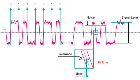
Measurement values of the fieldbus physical layer: Recorded per field device and segment, the FieldConnex Diagnostic Manager interprets them and displays the quality of transmission in easy to understand graphics and clear text.
Due to the Diagnostic Manager signal level, noise and jitter can easily be identified.
Signal Level
The signal level is the voltage of the communications signal that a device transmits on the fieldbus cable. It is generated through a current change created by the device. This current change is then “translated” into the voltage change detectable by all fieldbus participants through the terminators located at each end of the fieldbus trunk.
Noise
Noise is an unwanted disturbance that is induced in the fieldbus cable from outside sources, e.g., through EMI.
Jitter
Jitter is the deviation of the ideal zero crossing point of the transmitted signal curve during the nominal bit duration, measured with respect to the previous zero crossing point. This is an extremely sensitive measurement.
Any hardware connected to the fieldbus segment influences the electrical attributes of the segment. Each change in connected hardware causes a change in electrical parameters, which in turn changes the signal form and typically increases jitter:
- Cables with bad parameters
- Faulty components in an instrument
- Over or under termination
In reality, a system is able to run with higher jitter levels but with reduced immunity against EMI such as noise. The amount of jitter is only dependent on the quality of the connected components.
- Ask an Expert
- Cross Reference Request
- Check order status
- News
- Subscribe to Gate-Way, our Process Automation Division e-newsletter
- Service Level Agreements for ecom instruments
- Where to Buy our Products
- Browse Literature
- Technologies
- Control System Solutions
- Download Technical Documents
- Press Releases
- International Trade Shows
Get your free ADM Integration Package for your DCS System!
ABB 800xA Integration Package Download


Pepperl+Fuchs Inc.
1600 Enterprise Parkway
Twinsburg, OH 44087
USA
- responsible for Canada -
sales@us.pepperl-fuchs.com
 +1 330 425-3555
Pepperl+Fuchs is a leading developer and manufacturer of electronic sensors and components for the global automation market. Continuous innovation, enduring quality, and steady growth have been the foundation of our success for more than 70 years. Pepperl+Fuchs employs 6,300 people worldwide and has manufacturing facilities in Germany, USA, Singapore, Hungary, Indonesia and Vietnam, most of them ISO 9001 certified.